Professional Equipment Manufacturer
 Esperanto
 Shqiptare
 Euskara
 Zulu
Zulu
 Latinus
 Cymraeg
 தமிழ்
தமிழ்
 Slovak
 Slovak
 Afrikaans
DH-8600 flux paste
Categories:
Keywords:
Product introduction
Lead-free solder paste is not truly lead-free, but requires that the lead content must be less than 1000ppm (<0.1%), which also means that electronic manufacturing must comply with lead-free assembly process requirements. Six other toxic and hazardous materials including lead, including mercury (Hg), cadmium (Cd), hexavalent chromium (Cr), lead (Pb), polybrominated biphenyl (PBB), polybrominated diphenyl ether (PBDE), etc. The content must be controlled within the level of 1000ppm. It's called lead-free solder paste.
The composition of lead-free solder paste is mainly composed of tin/silver/copper, with silver and copper replacing the original lead components. 1. Fundamental characteristics and phenomena In the tin/silver/copper system, the metallurgical reaction between tin and secondary elements (silver and copper) is the main factor that determines the application temperature, solidification mechanism, and mechanical properties. According to the binary phase diagram, there are three possible binary eutectic reactions between these three elements. A reaction between silver and tin forms a eutectic structure between the tin matrix phase and the compound phase (Ag3Sn) between the ε metal at 221°C. Copper and tin react at 227°C to form a eutectic structure of the tin matrix phase and an eta intermetallic compound phase (Cu6Sn5). Silver can also react with copper to form a eutectic alloy of silver-rich alpha phase and copper-rich alpha phase at 779°C.However, in the current study, the curing temperature of the tin/silver/copper triple compound was measured and no phase transition was found at 779°C. This indicates that it is likely that silver and copper reacted directly in the triplet compound. In terms of temperature kinetics, it is more suitable for the reaction of silver or copper with tin to form Ag3Sn or Cu6Sn5 intermetallic compounds. Therefore, the tin/silver/copper triple reaction can be expected to include a tin matrix phase, an ε-metal combination phase (Ag3Sn), and an eta-metal combination phase (Cu6Sn5).
As confirmed for the dual-phase Sn/Ag and Sn/Cu systems, the relatively hard Ag3Sn and Cu6Sn5 particles in the Sn matrix Sn/Ag/Cu triple alloy can be effectively strengthened by establishing a long-term internal stress. alloy. These hard particles can also effectively block the spread of fatigue cracks. The formation of Ag3Sn and Cu6Sn5 particles can separate the smaller tin matrix particles. The smaller the Ag3Sn and Cu6Sn5 particles are, the more effectively they can separate the tin matrix particles, resulting in an overall finer microstructure. This facilitates sliding mechanisms at particle boundaries and therefore extends fatigue life at elevated temperatures.
Although the specific formulation of silver and copper in the alloy design is critical to obtain the mechanical properties of the alloy, the melting temperature was found to be insensitive to changes in the copper content of 0.5 to 3.0% copper and 3.0 to 4.7% silver.
The relationship between the mechanical properties of silver and copper contents is summarized as follows: when the silver content is about 3.0~3.1%, both the yield strength and the tensile strength increase almost linearly with the copper content to about 1.5%. increase. Above 1.5% copper, the yield strength will decrease, but the tensile strength of the alloy remains stable. The overall alloy plasticity is high for 0.5~1.5% copper and then decreases with further increase in copper. For silver content (copper in the range of 0.5~1.7%), both yield strength and tensile strength increase almost linearly with the silver content increasing to 4.1%, but the plasticity decreases.
At 3.0~3.1% silver, the fatigue life reaches the maximum at 1.5% copper. It was found that increasing the silver content from 3.0% to higher levels (up to 4.7%) did not produce any improvement in mechanical properties. When both copper and silver are formulated at high levels, the plasticity is compromised, such as 96.3Sn/4.7Ag/1.7Cu.
Technical requirements
Lead-free solder paste must first be able to truly meet environmental protection requirements. It cannot remove the lead and add new toxic or harmful substances; it must ensure the solderability and post-soldering reliability of the lead-free solder, and must take into account the customer costs and many other issues. To sum up, lead-free solder should try to meet the following requirements:
1.The melting point of lead-free solder should be low, as close as possible to the eutectic temperature of 63/37 tin-lead alloy of 183°C. If the eutectic temperature of the new product is only a few degrees higher than 183°C, it should not be a big problem, but it is not yet There is no such lead-free solder that can be truly promoted and meets the welding requirements; in addition, before developing a lead-free solder with a lower eutectic temperature, the melting interval temperature difference of the lead-free solder should be reduced as much as possible, that is, the melting interval temperature difference of the lead-free solder should be reduced as much as possible. Minimize the temperature range between the solidus line and the liquidus line. The minimum solidus temperature is 150℃, and the liquidus temperature depends on the specific application (wave soldering tin bar: below 265℃; tin wire: below 375℃ ;Solder paste for SMT: below 250℃, usually the reflow soldering temperature should be below 225~230℃).
2.Lead-free solder must have good wettability; generally, the time the solder stays above the liquidus line during reflow soldering is 30 to 90 seconds. During wave soldering, the soldered pins and circuit board substrate surface are in contact with the tin The contact time of the liquid wave peak is about 4 seconds. After using lead-free solder, it is necessary to ensure that the solder can show good wetting performance within the above time range to ensure high-quality soldering effect;
3.The electrical conductivity and thermal conductivity after soldering should be close to that of 63/37 tin-lead alloy solder;
4.The tensile strength, toughness, ductility and creep resistance of the solder joints must be similar to those of tin-lead alloy;
5. Reduce the cost as much as possible; currently, it can be controlled at 1.5 to 2 times that of tin-lead alloy, which is an ideal price;
6. During use, the developed lead-free solder has a good bond with the copper base of the circuit board, or the lead-free solder plated on the circuit board, as well as the component pins or the lead-free solder and other metal plating on its surface. brazing performance;
7. The newly developed lead-free solder should try its best to match all kinds of fluxes, and its compatibility should be as strong as possible; it can work with the support of active rosin resin flux (RA), and can also be applied to mild and weak soldering fluxes. Reactive rosin flux (RMA) or rosin resin-free no-clean flux is the future development trend;
8.It should be easy to inspect and repair the solder joints after soldering.
9. The raw materials selected can meet the long-term sufficient supply;
10. Compatible with the currently used equipment and technology, and can work without replacing the equipment.
FACTORY WORKSHOP


CUSTOMER TRANSACTION
Adhering to the business principle of mutual benefits, we have had a reliable reputation among our customers because of our professional services, quality products and competitive prices.

CUSTOMER TRANSACTION
We welcome customers at home and abroad to visit our factory to reach long-term cooperation and create success together.

FAQ

Can you make a proof for using automatic soldering station:

Yes, please send us your motherboards and components,we can even customize a jig/fixture which will hold your motherboard & components on Machine’s table for soldering.

What is a BGA reworkstation?

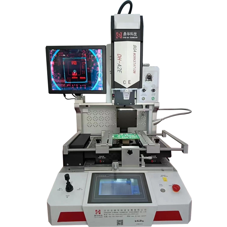
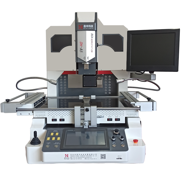
Dinghua BGA rework stations, featured with 3 independent heating-area, PID controlling temperatures, real-time curves displaying on touchscreen, is a station used for various chips and a few components desoldering or soldering.

Are you a manufacturer or a trading company?

We are a leading manufacturer of BGA rework station, Xray inspection machine, Xray counter machine and automation equipment etc

Where is your factory?

We are located at 4F 6B, Shengzuozhi Technology Park, Xinqiao, Bao’an, Shenzhen, Guangdong, China

Are there over-seas after-sales service centers?

BGA rework station, Xray inspection machine, Xray counter machine and automatic soldering station consist of modularized structures, which are simple to change. So, if machines have a problem, changing its relevant part. We don’t arrange after-sales engineers to always live overseas, but, if our customers need extra service, our engineers can go to on-site

Have you had experiences cooperating with cross-border enterprises by today?

Yes, we do. Such as, Google, Foxconn, Micron, Vestel, Huawei, Kinpo and BYD etc
Online Message


